Inclined Fin Heat sink in Natural Convection
Natural convection has been used to cool electronics for ages. It is a simple and reliable method. The big drawback, of coarse, is that the cooling capacity is limited. All possible means to enhance natural convection are therefore more than welcome. This article is about one particular method, inclined parallel plates.
My first encounter with this issue happened when I was trying to design a cooling system for active electronics mounted in radio masts. Fans were excluded for reliability reasons. The only realistic alternative was therefore natural convection. The equipment was enclosed in metal boxes that needed to be cooled from one side. Applying a wide but not very high heat sink could have solved the problem but horizontal structures are not considered esthetical in radio masts. A second restraint was therefore that the heat sink not could be made much wider than the mast itself.
I was about to give up on the problem when a colleague of mine came to my rescue. Supported by CFD calculations he suggested that there were gains to be made if the heat sink was made quite high and with inclined fins. Even if the project, for other reasons than thermal, later was abandoned, this discovery trigged me to find out more about the issue.
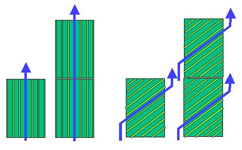
Fig.1: The air temperature increases is higher for heat sinks with vertical fins than heat sinks with inclined fins.
A first overview can be achieved with a very simple comparison. Fig.1 shows a heat sink with vertical fins and another one with inclined fins. It is somewhat difficult to compare their performance on single unit bases but if they are stacked things get much clearer. For the vertical arrangement it is apparent that the top heat sink is less effective than the bottom heat sink, because it receives heated air from below. For the inclined arrangement this is not the case. Each stacked unit will in fact approximately contribute as much as the units below. My first idea was therefore that there must be a critical height above which inclined fins perform better than the vertical fins. That turned out to be wrong! What I found was that inclined fins always perform better than vertical fins.
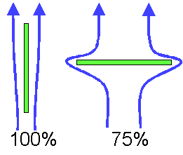
Fig.2: The angular orientation has a rather limited impact on the cooling of a single plate.
The angle impact
Basic heat transfer theory reveals that the angular orientation has a rather limited impact on the cooling of a single plate, Fig.2. For parallel plates there are reports that the angle does not have much impact either. Some reports even suggest no impact at all if the inclination angle is smaller than 60°. These observations are of coarse true but it is doubtful if they also are valid for closely spaced plates. This is important since the optimum spacing always is found in a region between single plate characteristics and closely spaced plates characteristics. See: A Volumetric Approach to Natural Convection.
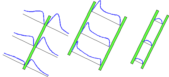
Fig.3: The asymmetry of the velocity profile must reasonably be less important for plates with a small spacing than for plates with large spacing.
A particular difficulty when dealing with inclined parallel plates is the asymmetric velocity profile. For single plates it is apparent that the velocity gradient is higher on the downward side than on the upward side. This is also the case for parallel plates separated by a large distance, Fig.3. For closely spaced plates it however seems reasonable to assume that the viscous forces are so strong that any important asymmetry not can be formed.
For plates with large spacing it is therefore reasonable to assume that the describing equations are independent of the inclination angle and the same as for parallel vertical plates. For plates with small spacing it is reasonable to assume that the velocity profile is symmetric. The describing equations would in that case also be the same as for vertical plates but with the difference that gravity is replaced by the gravity component in the plate direction.
The problem is to find a realistic approach for plates placed on optimum distance. A straightforward way could be to use the same method as for vertical plates, which is to let a smooth function operate on the two extreme cases small and large plate spacing. The drawback with this line of attack is that the optimisation equations become quite complex. Another possibility is to assume that the velocity profile is symmetric at optimum plate spacing. Both these methods were tried and the result difference was found to be minor.
The equations presented here are based on the latter assumption. Unfortunately there does not seem to exist any hard laboratory evidence that they are correct. Using the vocabulary that a theory is a confirmed hypothesis, what follows is definitely a hypothesis. The result is however so interesting that it is worth sharing with others.

Fig.4: Optimum equations.
First calculate the optimum plate angle
And then it able to get the optimum plate spacing
\(k_s\) value in the equation ref to below table.
Optimum equations
Fig.4 shows the optimum equations and table 1 the corresponding proportionality parameters. The equations are similar to those for vertical parallel plates but there are a couple of extra terms that handle the angle impact. It should also be noted that the optimum plate spacing is a function of the plate length, which in this case not is uniform. The plates in the corners must therefore be given a closer spacing than other plates.
| Air temp (°C) | \(K_s\) | \(K_v\) |
|---|---|---|
| -20 | 0.0226 | 116 |
| -10 | 0.0236 | 109 |
| 0 | 0.0247 | 104 |
| 10 | 0.0257 | 98.5 |
| 20 | 0.0268 | 93.9 |
| 30 | 0.0279 | 89.3 |
| 40 | 0.029 | 85.2 |
| 50 | 0.0301 | 81.5 |
| 60 | 0.0311 | 78 |
Table 1: Parameters for the equations in Fig.4.
Equation 3 is based on equation 2 but an efficiency term has been added. The idea behind this term is that it should take care of all deviations from ideal conditions such as non-isothermal plates, non-negligible plate thickness, non-optimum plate spacing and U-shaped flow channels. The temperature difference term has in addition been indexed to underline that the equation is valid for non-isothermal conditions. The order of the efficiency that can be achieved can probably vary considerably. Based on the experience for vertical plates a course estimate would be 70% – 90%.

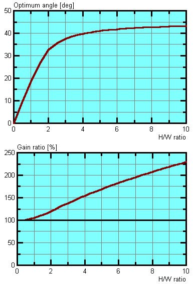
Fig.5: Optimum inclination angle and possible gains relative to vertical plates.
Figure 5 shows the optimum angle and the gains that can be made relative to vertical plates. The optimum angle is very small for low H/W ratios and it asymptotically approaches 45° for large H/W ratios. The heat dissipation relative to vertical plates is described by the “Kgamma” term in equation 2. This function is mapped in the lower image and it shows the somewhat surprising phenomenon that an inclination angle always is beneficial. The gains are however very modest for small H/W ratios.
Discussion
The benefits at H/W<1 are obviously too small to make inclined arrangements worthwhile. For higher H/W ratios there might however be some attractive cases. A coarse rule of thumb could be that the matter should be considered if H/W>4. The potential gain at this ratio is 50%, which could be a sufficient incitement to take the extra costs associated with an inclined arrangement.
It might be possible that a stack of inclined PCBs could be a solution to some odd problem but the major application for inclined plates is nevertheless heat sinks. There are nevertheless several practical problems associated with such designs. Manufacturing is one of them. Casting seems to be the only realistic alternative. Another difficulty is that a heat sink not is effective unless the base plate temperature is reasonably uniform. It is apparent that this can be difficult to arrange for high but not very wide heat sinks. A chimney arrangement, that occupies the same volume but where the heat sink itself is much smaller, could therefore be a more attractive solution. An additional problem is that heat sinks with inclined fins not can be placed side by side.
Even if there are few attractive applications for electronics there is however one that seems to be both realistic and beneficial: cooling of high voltage transformers. These devices often have a considerable H/W ratio and their cooling fins seem to be manufactured by casting.
Article written by Ake Malhammar, Heat Transfer expert. Reproduced by kind permission in the Mechanical Design Forum. Link to original source material is here: http://frigprim.x10.mx/articels2/parallel_pl_Inc.html